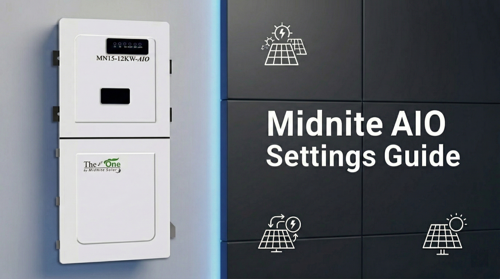
 The Midnite AIO is a great inverter, but the installation and user guide is lacking clarity and detail. I created a more detailed programming guide to help explain what each setting does. This is not intended to cover all scenarios, and this information is not from the manufacturer, so take it for what it is worth. Disclaimer: I take no responsibility for your use of the information presented here. Always follow manufacturer instructions.
When programming the Midnite AIO, note that some settings require that the inverter(s) are in standby mode. Other settings can be done with the inverter(s) operating. When programming inverters that are in parallel operation, always check that the settings propagate to all connected inverters to avoid issues.
Finally, note that the availability of specific settings may differ based on firmware version. Enjoy the guide and leave comments below if you have any questions or suggestions.
Interactive reference for the MidNite MN 15-12K AIO inverter settings as shown in the MidNite Pro app. Click any setting name to expand a detailed explanation. Descriptions are based on the MidNite AIO Programming Guide and the official installation manual. Values shown are examples only.
Battery Communication
Settings, labels, and example values update based on your selections.
1. Power Control
Configure the device’s power settings, meter parameters, and energy flow.
| Setting | Value |
|---|---|
Work mode
The primary operating mode of the inverter.
Self Consumption: Excess solar charges batteries first. Once full, excess exports to the grid (up to the allowed limit, or zero if Zero Export is on). When solar is insufficient, batteries supply loads until the on-grid discharge limit, then grid takes over. Grid Feed In Priority: Excess solar exports to the grid rather than charging batteries. Batteries only charge/discharge via Time Base Control schedules. Maximizes grid export; battery reserved for outages or scheduled windows. Off Grid: No grid connection. No cables on “AC Grid” terminals (though they can be used for a second generator). Inverter supplies backup loads from solar and battery. If grid fails in any other mode, the inverter automatically switches to off-grid behavior. Select different inverter modes
|
Off GridSelf Consumption |
Support normal load
Controls whether the inverter offsets loads on the non-backed-up (“normal”) side of the panel using CT sensor readings, in addition to the backed-up loads. When disabled, the inverter only serves loads wired to its backup output terminals. If the grid fails, power is only fed to backed-up loads regardless of this setting. Enable in self-consumption or time-of-use scenarios to maximize solar/battery value across the entire home.
Select whether to support the loads on the grid side
|
● (toggle) |
Zero export
Controls whether the system can export power to the grid. When enabled, the inverter curtails solar once batteries are full and loads are met, preventing any backfeed. Required when operating without an interconnection agreement. Even with Zero Export on, brief overshoot can occur when large loads drop off, which is why the “Maximum consumption from grid” buffer setting exists.
Select whether enable power exporting to the grid
|
● (toggle) |
Smart load Smart load port function setting
| Smart Load 1 (Gen) — Adjust in Standby Mode | |
Smart Load 1 mode
Selects the function for the Smart Load 1 port (60A rated). Options: Not enabled, Generator, or Smart load. When set to Generator, this port becomes the generator input with automatic start/stop control via dry contacts, and the settings below become active. When set to Smart load, the output turns off below a set battery level and back on at a higher level. Changes to this setting require the inverter to be in Standby mode.
|
Generator |
Maximum input power from generator
Maximum total power the inverter will accept from the generator, including both pass-through to loads and battery charging combined. Range: 0 to 30,000W (up to two paralleled inverters can share the generator input). Set this to match the generator’s rated continuous output to prevent overloading it.
|
30000 W |
Maximum Generator charge power
Maximum power from the generator that can be directed to battery charging specifically. Range: 0 to 20,000W. The remainder of generator power (up to the max input power) is available for loads. This prevents the battery charger from consuming all the generator’s output and starving the loads. Set based on the battery manufacturer’s max charge rate and the generator’s capacity after accounting for expected loads.
|
20000 W |
Generator start and stop by battery voltageGenerator start and stop by battery SOC
The battery level that triggers the generator dry contact signal to start, and the level at which it signals to stop. The first value is the start threshold (generator turns on when battery drops to this level). The second value is the stop threshold (generator turns off when battery charges back up to this level). There is no ramping on generator start/stop. Set the start point low enough to avoid unnecessary generator runs, but high enough to prevent deep discharge damage. The stop point should allow the battery to reach a healthy charge level before shutting the generator off.
Generator dry contact signal on/off trigger point
|
54.4 V, 55.1 V40 %, 80 % |
Generator standby and max run time
Two values: standby time and maximum run time, both in minutes. Standby time is how long the generator continues running after charging stops, allowing it to cool down under light load before shutting off. Max run time is the maximum continuous minutes the generator can run at a time, even if charging is not complete. After hitting the max run time, the generator shuts off for the standby period before potentially restarting if the battery is still below the start threshold. Setting both to 0 disables these limits.
Generator standby time after max run time, and max run time setting
|
0 Min, 0 Min |
AGS (Auto Generator Start)
Controls the dry contact signal to the generator. Options: Auto (generator starts and stops automatically based on the battery voltage/SOC trigger points above), On (dry contact held closed, forcing generator to run continuously), or Off (dry contact held open, generator will not start regardless of battery level). “Auto” is the normal operating setting. “On” can be used to force-run the generator for maintenance or emergency charging. “Off” disables automatic generator start.
Dry contact signal: Auto/On/Off
|
On |
Generator Dry Contact Wake-Up
Enables or disables the dry contact wake-up function for the generator. When enabled, the inverter can use the dry contact relay to send a start signal to generators that require a contact closure to initiate startup (most modern auto-start generators). Some generators use their own internal auto-start logic and only need an enable signal, while others need a momentary or sustained contact closure.
|
● (toggle) |
Run Cycle
Sets an automatic exercise cycle for the generator. Options: Disable, Weekly, or Monthly. Generator exercise cycles run the generator briefly on a schedule to keep it in working order, circulate oil, charge the starter battery, and verify it will start when needed. Important for standby generators that may sit idle for weeks or months between outages.
Disable or run once every week/month
|
Disable |
| Smart Load 2 (50A) | |
Smart Load 2 mode
Selects the function for the Smart Load 2 port (50A rated). Options: Not enabled, Smart load, or AC Coupling. When set to AC Coupling, this port accepts input from a grid-tied string or micro-inverter system (such as Enphase or SolarEdge) and the settings below become active. The inverter can then manage the AC-coupled array by raising output frequency to throttle compliant inverters when batteries are full or the system is off-grid. When set to Smart load, the output turns off/on based on battery level.
|
AC Coupling |
AC coupling start and stop by battery voltageAC coupling start and stop by battery SOC
Controls when the AC-coupled PV array is turned on and off based on battery level. The first value is the level at which the AC-coupled array turns back on (battery needs charging). The second value is the level at which it turns off (battery is full enough). For example, setting 55V/57V (or 95%/100% in SOC mode) would turn the array off when batteries reach the upper limit and back on when they drop to the lower limit. This prevents overcharging while maximizing solar harvest.
AC coupling on/off trigger point by battery voltagebattery SOC
|
55 V, 57 V95 %, 100 % |
Off network output maximum frequency
When the grid is down (or in Off Grid mode) and the AC-coupled PV array is producing more power than the loads and battery can absorb, the inverter raises its output frequency to signal UL 1741SA/SB compliant grid-tied inverters to throttle or shut down. This setting controls the maximum frequency the inverter will ramp up to. Standard grid-tied inverters will begin reducing output around 60.5 Hz and shut down completely by the frequency set here. If the AC-coupled inverter is not frequency-responsive (not UL 1741SA/SB compliant), this feature will not work and overcharging or overvoltage can result.
Off network frequency setting
|
61 Hz |
| Smart Load 3 (30A) | |
Smart Load 3 mode
Selects the function for the Smart Load 3 port (30A rated). Options: Not enabled or Smart load. This port does not support Generator or AC Coupling functions. In Smart load mode, the output turns off when the battery drops below the lower threshold and turns back on when it charges above the upper threshold. Useful for shedding non-essential loads (pool pumps, water heaters, EV chargers) during low battery conditions to preserve capacity for critical loads.
|
Smart load |
Smart load stop and start by battery voltageSmart load stop and start by battery SOC
The battery levels that control when this smart load output turns off and back on. The first value is the lower threshold (output turns off when battery drops to this level). The second value is the upper threshold (output turns back on when battery charges to this level). The gap between the two values provides hysteresis to prevent rapid cycling of the connected load.
Smart load on/off trigger point by battery voltagebattery SOC
|
52 V, 53.5 V50 %, 80 % |
| Generator on Grid Side | |
Generator input location
Controls where the generator connects to the inverter. When disabled (default), the generator connects to the Smart Load 1/Gen input terminals. When enabled, the generator instead connects to the AC Grid input terminals, which can accept a larger amperage generator. This is useful if the generator exceeds the 60A rating of the Smart Load 1 port, or if a second generator input is needed. When using the AC Grid input for a generator in off-grid mode, “Charge by grid” must be enabled in the Battery settings.
Enable Generator on AC-in instead of Smartload1-Gen-in
|
● (toggle) |
Power Control
Enables or disables the PCS-ESS active power control function. Options include Disable, CT, and Smart Meter. When set to CT or Smart Meter, the inverter actively manages power flow based on sensor readings and the configured work mode. “Disable” is typical for off-grid systems with no grid interaction. “Smart meter” or “CT” should be selected for any grid-interactive system (self-consumption, zero export, time-of-use). The choice between CT and Smart Meter depends on which metering hardware is installed.
|
DisableSmart meter |
Sensor location
Specifies where the CT sensors or smart meter are installed relative to the inverter’s grid connection. Options are Grid side or Load side. Getting this wrong causes the inverter to misread the direction and magnitude of grid power flow.
|
Grid side |
Energy flow direction
Indicates CT sensor orientation. Arrows should face toward the inverter. If both CTs are installed backwards, flip this in software. Only use if both are backwards. If only one is backwards, it must be physically corrected.
|
From grid to inverter |
Power derating control method
PCS-ESS setting for how the inverter manages power across the two legs of a split-phase system. Options: minimum phase, total of both phases, or independent phase power. Generally should not be changed from default except under engineering supervision.
|
Independent phase power |
Maximum feed in grid power
Maximum power the inverter can export to the grid. Range: 0W to 11,400W. Set to 0 when Zero Export is enabled. May need to be limited for NEC 705.12(B) compliance (120% rule for backfed breakers) or per the utility interconnection agreement.
|
0 W11400 W |
Maximum consumption from grid
A small positive import buffer (in watts) the inverter maintains from the grid to prevent accidental export in Zero Export mode. Range: 30 to 500W. When a large load suddenly turns off, the inverter can briefly overshoot and export before responding. This buffer prevents that. Higher values = more protection against accidental export but higher grid consumption. Modern smart meters can detect even brief export when no interconnection agreement exists.
|
300 W30 W |
Meter type
Selects the smart meter model installed for grid power measurement. Only visible when Power Control is set to “Smart meter.” The meter must be compatible with the inverter’s Modbus communication protocol. Common options include CHINT/DTSU666 and other Modbus-compatible energy meters. The meter provides more accurate power flow data than CTs alone, particularly for larger or three-phase systems.
|
CHINT/ DTSU666 |
Modbus address
The Modbus communication address assigned to the energy meter. Only visible when Power Control is set to “Smart meter.” This must match the address configured on the physical meter itself. Default is 1. If multiple meters are on the same RS485 bus, each must have a unique address.
Modbus address for energy meter
|
1 |
| Battery Schedule | |
TimeBase control
Enables time-based scheduling for battery charge and discharge. Provides up to three charge and three discharge periods with independent start/end times (24-hour format), power rates (0-10,000W), and stop SOC/voltage for each. Overrides the Work Mode during programmed periods. Periods may not overlap. Set both start and end to 0:00 to disable a period. Can repeat daily or run once. If “Charge by grid” is disabled, scheduled charging uses only available solar after loads are met. Schedules cannot vary by season automatically and may need manual adjustment for seasonal rate changes.
Battery charge/discharge schedule
|
● (toggle) |
2. Battery
Configure the energy storage mode, charging, discharging, and backup settings.
| Setting | Value |
|---|---|
| Battery | |
Battery brand selection
Selects the battery communication protocol. Choosing a named brand (PYLON, UZ, MidNite) enables closed loop CAN/RS485 communication, allowing the BMS to report SOC, cell voltages, temperatures, and charge/discharge limits directly. “Lead Acid” or “Lithium Battery (without COMM)” runs in open loop mode using voltage-based estimation only. Closed loop systems show fewer settings on this page because the BMS manages charge parameters directly.
|
Lithium Battery (without COMM)MidNite battery |
Communication address
The CAN/RS485 communication address for the battery BMS. Closed loop batteries only. Must match the address configured on the battery BMS. Default is 1. In parallel inverter systems with independent batteries, each inverter-battery pair may need a unique address.
|
1 |
Battery capacity
Total battery bank capacity in amp-hours. Range: 0 to 65,535 Ah. Open loop only. Used for SOC estimation by coulomb counting. Multiply by nominal voltage for watt-hours.
|
1200 Ah |
Battery charge efficiency
Round-trip efficiency percentage. Range: 0-100%. Open loop only. Used for coulomb counting. Lithium: 95-98%. Lead acid: 80-85%.
|
97 % |
Battery Rate Temperature
Reference temperature for capacity rating. Open loop only. Most batteries are rated at 25°C. Used for temperature compensation, primarily for lead acid.
|
25 °C |
Lead-acid battery impedance
Internal impedance in milliohms. Range: 0-500 mΩ. Lead acid only. Compensates voltage readings under load. Not used for lithium.
|
5 mΩ |
Floating charge voltage
Float voltage. Range: 40-64V. Open loop only. For lithium, often set equal to absorb. Divide by cell count to verify per-cell voltage.
|
55.1 V |
Float voltage offset
Voltage drop below float that triggers a return to bulk charging. 0V disables. Open loop only.
Offset below float setpoint to re-start bulk charging
|
0 V |
Absorb voltage setpoint
Bulk/absorb voltage target. Range: 48-65V. Open loop only. For lithium, typically same as float. Verify per-cell voltage against manufacturer specs.
|
55.1 V |
Absorb voltage buffer
Buffer below absorb that resets absorb timer. 0V means timer runs once. Open loop only.
Offset below absorb voltage to restart absorb timer
|
0 V |
Stop discharge voltage
Low voltage disconnect (LVD). Range: 40-64V. Open loop only. Absolute floor for discharge. Parasitic draw continues after shutdown.
|
47.8 V |
EQ voltage
Equalization voltage. Range: 48-65V. Flooded lead acid only. Disable for lithium by setting EQ Time to 0.
|
54.5 V |
EQ Time
EQ duration in minutes. Range: 5-900. Flooded lead acid only. Set to 0 to disable. Must be 0 for lithium.
|
0 min |
Maximum allowed time to try to EQ
Max minutes to reach EQ voltage before aborting. Flooded lead acid only. Inactive when EQ Time is 0.
|
5 min |
Days between Automatic EQ charges
Auto-EQ interval in days. Flooded lead acid only. Set to 0 to disable. Must be 0 for lithium.
|
0 Day |
Force EQ charge now
Manually triggers EQ. Flooded lead acid only. Do not use on lithium. One-time trigger.
|
● (toggle) |
Capacity type
Determines whether the inverter uses SOC (percentage) or Voltage for all charge/discharge thresholds. Closed loop should use SOC. Open loop is more reliable with Voltage since the inverter lacks BMS data for accurate SOC. This changes how every other battery threshold is expressed.
Should be SOC type for closed loop lithium batteries only
|
VoltageSOC |
Discharge and charge to (V)Discharge and charge to (%)
Absolute lower and upper limits for battery usage across all modes. Hard boundaries for all battery operation, overriding work modes and schedules. After a low-voltage/SOC shutdown, parasitic draw from the inverter’s control board continues.
Voltage range for battery usageSOC% range for battery usage
|
47.8 V, 55.1 V18 %, 100 % |
Start and stop recovery charging when reaching (V)Start and stop recovery charging when reaching (%)
Voltage/SOC window for reduced-rate recovery charging of a deeply discharged battery. Between these values, the inverter limits charge rate to the “Maximum grid recovery charge power” setting. Protects deeply depleted cells from damage caused by high charge current.
Battery recovery charge trigger point by voltageBattery recovery charge trigger point by SOC
|
47 V, 48.5 V10 %, 15 % |
Discharge end voltage (on-grid)Discharge end SOC (on-grid)
Minimum battery level the system will discharge to while connected to the grid. The reserve for backup power. The inverter stops pulling from batteries at this level, preserving remaining capacity for outages. Accessible from the end-user login: raise before a storm for more reserve, lower to maximize daily cycling.
Battery capacity reserved for off-grid use by voltageBattery capacity reserved for off-grid use by SOC
|
50.4 V95 % |
Charge voltage buffer
Voltage offset above absorb/float setpoints. 0V = no buffer. Open loop only. Rarely needed for lithium.
Buffer above absorb and float setpoint
|
0 V |
Maximum charge power
Maximum total charging power from all combined sources: solar, generator, and grid. Range: 0-10,000W. Set per the battery manufacturer’s max charge rate.
Maximum allowable power for battery charging
|
10000 W |
Absorb time
Hold time at absorb voltage in minutes. Open loop only. 0 = skip absorb (typical for lithium). Lead acid: 60-120 min.
|
0 min |
Maximum discharge power
Maximum power the inverter can draw from the battery. Range: 0-10,000W. Overload shutdown possible off-grid if load exceeds this. On-grid, grid supplements.
Maximum allowable power for battery discharge
|
10000 W |
Maximum grid recovery charge power
Max charge rate during the recovery charging window. Gently brings deeply discharged batteries back before applying full charge current.
Maximum charging power from the grid during recovery charging
|
1000 W |
| Grid Charge | |
Charge by grid
Enables/disables grid charging. If disabled, batteries charge only from solar or generator. Some utilities prohibit grid charging, and ITC eligibility can be affected. Off-grid with this enabled allows the AC grid terminals as a generator input (up to 100A). Combined with “Force Charging,” grid charges regardless of schedules.
Enable charging from the grid while in off-grid mode
|
Enabled (on) |
Stop charging by battery voltageStop charging by battery capacity
The maximum battery level that grid charging will target. This is the ceiling for grid-sourced charging specifically, and the target “Force Charging” charges to. Can be set independently of the absorb voltage/SOC, so grid charging can target a different maximum than solar. For open loop, divide by cell count to verify per-cell voltage.
Grid charge stop voltageGrid charge stop SOC
|
57 V100 % |
Maximum allowed charging power
Max charge rate from grid only. Range: 0-10,000W. Time Base Control can set lower limits for scheduled windows. Works with overall “Maximum charge power” cap.
|
10000 W |
Stop Discharge reconnect voltage when off-grid
After a low-voltage shutdown, the voltage the battery must recover to before AC output resumes. The gap provides hysteresis to prevent rapid on/off cycling. On-grid, recovery charging starts instead of waiting.
Voltage at which battery reconnects after reaching end of discharge (EOD)
|
48 V |
Min. initiation/startup battery capacity when off-grid
After a low-SOC shutdown, the SOC the battery must recover to before the inverter turns AC output back on. This is the closed-loop equivalent of “Stop Discharge reconnect voltage.” The gap between shutdown SOC and this reconnect SOC provides hysteresis to prevent rapid on/off cycling. On-grid, recovery charging starts instead of waiting.
SOC at which the battery reconnects when the grid is unavailable after reaching end of discharge (EOD)
|
30 % |
Force charging
Grid or generator charges the battery regardless of other settings, including “Charge by grid” being off or Time Base Control schedules. Solar used first if sufficient. Charges to the grid charge stop target. Accessible from end-user login for storm prep. Combined with raising on-grid discharge reserve, this maximizes backup readiness.
If enabled, grid or generator charges battery regardless, unless PV is sufficient
|
● (toggle) |
3. General
Configure PV protection and multi-inverter system settings.
| Setting | Value |
|---|---|
| Protection | |
Enable low voltage ride through
Controls disconnect speed during brownouts. When enabled, the inverter rides through brief voltage sags to support the grid. Some utilities require this for interconnection. When disabled, disconnects faster during brownouts.
|
● (toggle) |
Enable Anti-Islanding
Ensures the inverter stops exporting when utility power is lost, preventing energized lines that workers assume are dead. Must be enabled for any grid-tied system. Only disable for special microgrids under engineering supervision.
|
● (toggle) |
PV Insulation resistance protection point
Minimum acceptable insulation resistance between PV conductors and ground. Range: 10-2,000 kΩ. If below this threshold during startup ground fault test, the inverter displays a ground fault error and shuts down. Low readings indicate damaged insulation, moisture intrusion, or a ground fault.
|
10 kΩ |
PV Leakage current protection point
Max allowable PV leakage current before ground fault shutdown. Range: 1-1,250 mA. Measured continuously during operation. The default is very sensitive. Poor quality MC4 connectors in wet conditions can cause nuisance tripping. Raise cautiously only after verifying no real ground fault exists.
|
1250 mA |
Derating setting
PCS-ESS power derating percentage. Range: 0-110%. Leave at default. Factory/engineering parameter.
Inverter power derate setting
|
110 % |
| Other | |
Grid voltage type
AC voltage topology. Options: Single Phase, UL Split Phase, UL 2/3 Phase (two phases of 120/208V). UL Split Phase is standard for US residential 120/240V. Must be correct before connecting to grid.
|
UL Split Phase |
Parallel single to three phase system
Phase position when multiple inverters form a three-phase system. Only relevant for three-phase parallel configurations.
Phase position of 3 phase parallel system
|
Unknown |
Buzzer
Audible beep when buttons are pressed. User preference only.
|
● (toggle) |
DRM Function
Demand Response Mode. Implements grid support functions (frequency-watt, etc.) per IEEE 1547 and UL 1741SA/SB. May be required by some utilities for interconnection.
|
● (toggle) |
Parallel mode
Enables parallel operation with other AIO units. Up to 9 inverters can be paralleled. DIP switches must be ON for 2-unit parallel. Communication cable must be connected between units first. See installation manual for wiring and DIP switch configurations.
|
● (toggle) |
Parallel system battery connect type
In parallel systems: Parallel means all inverters share one battery bank (master manages, status on master only). Independent means each inverter has its own battery. Use “parallel” when sharing a common battery bus; “independent” when each unit has a separate battery stack.
Select parallel/independent battery in parallel system
|
Battery connect parallel |
4. Grid
Configure the power grid standard code, power-on and reconnection parameters, and voltage and frequency protection.
| Setting | Value |
|---|---|
Grid Standard Code
Grid interconnection standard. IEEE 1547 is standard for US inverters. Changing this resets all protection parameters below to the new standard’s defaults.
|
▸ (sub-menu) |
Maximum input power from grid
Max total power from grid (pass-through to loads + battery charging). Range: 0-24,000W. Reduce if the grid breaker is under 100A continuous. Can also limit peak demand on weak grids or high demand-charge areas.
Power limitation of taking power from AC grid
|
10000 W |
| Start-Up Time and Power Ramp-Up Rate | |
First boot
Startup delay and power ramp rate on initial power-on. First value = seconds before export begins. Second = ramp rate in %/min. Prevents sudden power injection that could disturb the grid or trip protection.
|
10 s, 20 %/min |
Reconnect and boot
Delay and ramp rate when reconnecting after a grid disconnection event. Works like “First boot” but for reconnection. The IEEE 1547 default 300-second wait is often excessive. 10-20 seconds with 20%/second ramp is commonly used where permitted.
|
10 s, 20 %/min |
Grid first Voltage
Voltage window the grid must be within before initial connection. Lower and upper limits, phase to neutral.
|
110 V, 126 V |
Grid first Frequency
Frequency window the grid must be within before initial connection. Normal US grid: 60.0 Hz.
|
59.5 Hz, 60.1 Hz |
Grid Reconnection Voltage
Voltage window for reconnection after a disconnection event. Grid must be stable within this range during the reconnection delay.
|
110 V, 126 V |
Grid Reconnection Frequency
Frequency window for reconnection after a disconnection event.
|
59.5 Hz, 60.1 Hz |
| Low Frequency Protection | |
Protection Level 2&1
Under-frequency disconnect thresholds. Level 1 (moderate): grid overloaded, rides through for the Level 1 time. Level 2 (severe): disconnects almost immediately. Standard: L1=58.5 Hz, L2=56.5 Hz. Do not change without utility approval.
|
56.5 Hz, 58.5 Hz |
Protection Time Level 2&1
Time delays for under-frequency protection. L2 (severe): 160 ms (one AC cycle). L1 (moderate): 300,000 ms (5 min ride-through). Do not change without utility approval.
|
160 ms, 300000 ms |
| High Frequency Protection | |
Protection Level 1 & 2
Over-frequency thresholds. Standard: L1=61.2 Hz, L2=62.0 Hz. Do not change without utility approval.
|
61.2 Hz, 62 Hz |
Protection Time Level 1 & 2
L1 (moderate): 300,000 ms ride-through. L2 (severe): 160 ms disconnect. Do not change without utility approval.
|
300000 ms, 160 ms |
| Low Voltage Protection | |
Protection Level 2&1
Under-voltage thresholds (phase to neutral). Standard: L1=105.6V (88% nominal), L2=60V (severe fault). Do not change without utility approval.
|
60 V, 105.6 V |
Protection Time Level 2&1
L2 (severe, below 60V): 2,000 ms. L1 (moderate, below 105.6V): 21,000 ms. Do not change without utility approval.
|
2000 ms, 21000 ms |
| High Voltage Protection | |
Protection Level 1 & 2
Over-voltage thresholds. Standard: L1=132V (110% nominal), L2=144V (120% nominal). Do not change without utility approval.
|
132 V, 144 V |
Protection Time Level 1 & 2
L1 (above 132V): 13,000 ms. L2 (above 144V): 160 ms. Do not change without utility approval.
|
13000 ms, 160 ms |
| Reactive Power Control | |
Reactive power control
Sub-menu for VAR behavior: Pure Merit, Cos Phi, Constant, Cos Phi(P), Q(U), Q(P). Do not change from defaults unless required by utility. Also includes Reactive Power Control Time (ramp rate). The default 300-second wait is excessive; 10-20 seconds at 20%/second is recommended.
|
▸ (sub-menu) |
5. Communication
Configure the WiFi hotspot for communicating with the MidNite Pro app. Enter the WiFi SSID and password for the inverter’s built-in WiFi/Ethernet dongle, used for local monitoring, remote monitoring, and firmware updates.
Important: The inverter must be in Standby mode and Parallel mode must be disabled before WiFi parameters can be changed.
Note: Values shown are examples only. Settings labeled “open loop only” apply when Battery Brand Selection is set to a non-communicating option. Closed loop configurations show fewer battery settings because the BMS manages charge parameters directly. Grid protection settings should not be modified without utility approval. Descriptions based on the MidNite AIO Programming Guide and official installation manual.