
Time to nerd out a bit. How about a story about voltage rise and why it isn’t as big a problem in the off-grid world? Grab a cup of coffee. You might need it. 🙂
The Wire Size Nobody Questions
I recently reviewed engineering plans for a large off-grid solar project on a barrier island in Southwest Florida. The system includes 68 Enphase IQ8A microinverters on the main house, AC coupled through a long feeder run to a detached garage where the battery inverters and all the power electronics live. The engineer had spec’d the AC conductors from the main house to the garage at a size that would make any grid-tied designer nod approvingly. Nice, fat, expensive copper. Textbook voltage drop compliance.
There was just one problem. This system will never be connected to the utility grid. There is no FPL meter. There is no net metering. And the two reasons engineers oversize conductors on long AC runs, voltage drop and voltage rise, simply do not carry the same weight on an off-grid system. By defaulting to grid-tied assumptions, the engineering plans were adding over ten thousand dollars in copper cost that the homeowner did not need to spend.
I flagged it. The engineer agreed it was worth revisiting. And it got me thinking about how many off-grid projects across the country are carrying inflated wire costs because designers are applying grid-tied thinking without stopping to ask whether it still applies.
Two Problems, One Conductor
Before we get into why off-grid changes the equation, it helps to understand the two separate concerns that drive conductor sizing on solar AC circuits. They are related but distinct, and most homeowners (and plenty of engineers) conflate them.
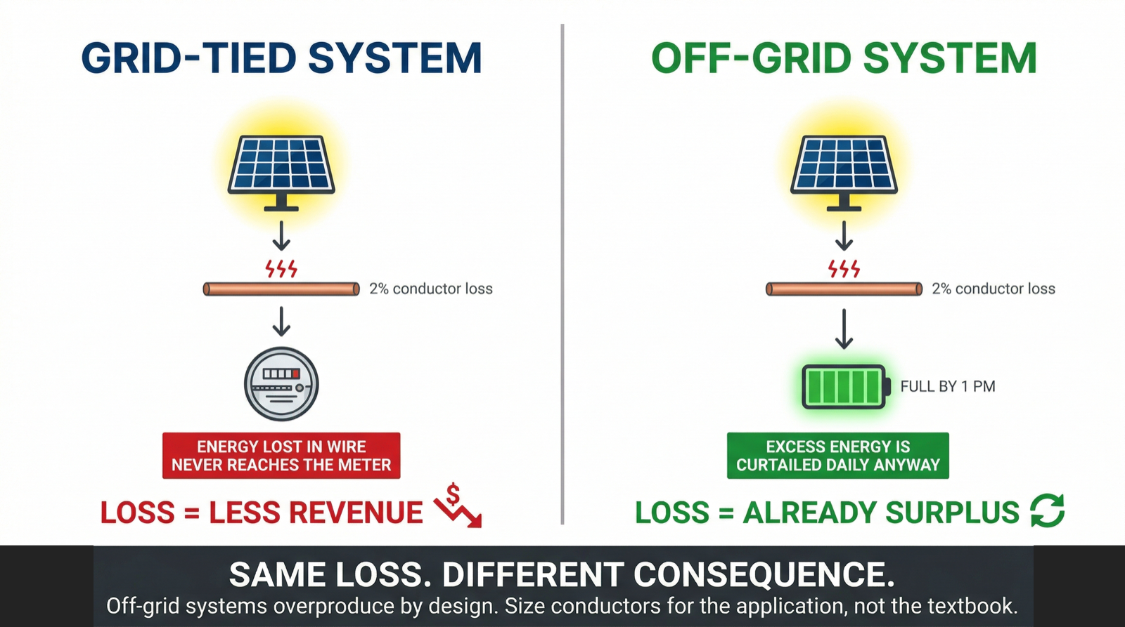
Voltage drop is the energy lost as heat in the conductor due to its resistance. Current flows through the wire, the wire has resistance, and some energy is dissipated along the way. The longer the run and the smaller the wire, the more energy you lose. On a grid-tied system, this lost energy is energy that never reaches the utility meter, which means you produced it but never get credit for it.
Voltage rise is the increase in voltage at the source end of the conductor (where the microinverters are) relative to the receiving end (where the battery inverter or panel is). When microinverters push current through a long conductor, the voltage at their terminals rises above the voltage at the other end of the wire. If it rises too high, the microinverter will throttle back or shut down to protect itself and comply with its UL listing. This is the operational performance concern.
On a grid-tied system, both of these matter. Voltage drop costs you money over time. Voltage rise can cause inverter shutdowns and lost production. Engineers size conductors to manage both, and the NEC informational notes in sections 210.19 and 215.2 recommend limiting voltage drop to 3% on individual circuits and 5% total on the combined feeder and branch circuit path. These are recommendations, not requirements, but following them is standard practice.
Bigger wire is always better… until you consider the cost!
For an off-grid system, the calculus for both voltage drop and voltage rise changes significantly.
Voltage Drop: No Meter, No Problem
On a grid-tied solar installation, voltage drop is a real financial concern. Every watt your solar panels produce needs to travel through conductors to the inverter, through more conductors to the electrical panel, and eventually out to the utility meter. The meter is what counts. If voltage drop in the conductors causes even a small percentage of energy to dissipate as heat, that energy never gets recorded. You produced it, but you do not get credit for it.
Over 25 years, that adds up. A 2% loss on a 20 kW system producing 28,000 kWh per year is 560 kWh per year, or 14,000 kWh over the life of the system. At current FPL rates, that is real money walking out the door.
Off-grid systems do not have a utility meter. There is no net metering credit. There is no export. Every kilowatt-hour the solar array produces is either consumed by the home’s loads, stored in batteries, or curtailed because the batteries are full and the loads are satisfied. That is the entire universe of outcomes.
When AC-coupled microinverters push power through a long feeder run to the battery inverter in a detached structure, yes, there is some energy lost as heat in the conductors. That is physics, and it is unavoidable regardless of wire size. But that lost energy is not revenue. It is a small reduction in the amount of energy available for storage or consumption, and in most well-designed off-grid systems, the solar array is already deliberately oversized to handle shorter winter days and cloudy stretches. A small percentage of conductor loss during peak production hours is noise within the built-in surplus.
The energy “lost” to voltage drop in the conductor was going to be curtailed anyway once the batteries fill up. You are not losing money. You are losing a tiny fraction of energy that the system was designed to produce in excess.
Voltage Rise: Why the Microinverters Will Be Fine
This is the part that makes engineers nervous, and understandably so. If you downsize the conductors on a long AC feeder, the voltage rise at the microinverter terminals increases. Every microinverter has an operational voltage window defined by its UL listing, and if the terminal voltage exceeds the upper limit, the unit will reduce output or disconnect entirely. On paper, that sounds like a performance risk you should not accept.
In practice, on an off-grid system with a well-understood load profile, the risk is far smaller than it appears.
On a grid-tied system connected to FPL, the utility grid acts as a stiff voltage reference. The grid voltage is what it is, and the microinverter has to work within that context. If the local grid voltage is already running high (which is common in Southwest Florida, where FPL often delivers 245 to 248 volts on a nominal 240-volt service), the headroom for voltage rise on the solar circuit gets tight. Oversizing conductors to minimize rise is the right call.
On an off-grid system, the voltage reference is set by the battery inverter. In the project I reviewed, that is an EG4 FlexBOSS, which generates its own AC waveform at a controlled voltage. The starting point is not an unpredictable utility voltage. It is a known, configured value. That gives you more headroom to begin with.
But the bigger factor is how microinverter arrays actually behave in real-world conditions. The theoretical maximum current on this 68-unit array is calculated using each microinverter’s maximum continuous output: 1.45 amps times 68 units equals 98.6 amps on the feeder. That is the number the engineer uses to calculate voltage rise at the microinverter terminals. And at that current, with undersized conductors, yes, the voltage rise could look concerning on paper.
Here is the thing. That theoretical maximum almost never occurs.
The 68 panels on this project are spread across a relatively flat roof with slightly different orientations. Some face slightly more south, some slightly more west. They are not all hitting peak irradiance at the same instant. Cloud shadows move across the array. Soiling varies. Temperature affects output. The real-world operating current on the feeder is virtually always lower than the calculated maximum, often significantly lower.
When I told the engineer that the voltage rise associated with realistic operating conditions would not put the microinverters outside their operational window, that was based on understanding both the equipment specs and how these arrays actually perform in the field. The IQ8A has a wide operating voltage range. The GridBoss is generating a clean, stable voltage reference at a configurable setpoint. And the array is physically incapable of sustaining the theoretical maximum current that would create a voltage rise problem.
The Real Numbers
Let me put some rough numbers on this so it is not abstract.
On this project, the one-way feeder run from the main house to the garage is well over 100 feet. At 98.6 amps (the theoretical max), the difference between spec’ing conductors for a strict 2% voltage drop on the feeder versus accepting a 4% or even 5% drop is significant in terms of wire gauge.
Going from, say, 400 Kcmil copper to 4/0 AWG or even 3/0 AWG copper on a run that long, with multiple conductors in conduit, can save hundreds of dollars per conductor. Multiply that across the full circuit (two hots, a neutral, and a ground), factor in the conduit fill implications of smaller conductors potentially allowing smaller conduit, and the savings can easily reach several thousand dollars on a project like this.
On a grid-tied system, I would never recommend accepting that extra voltage drop or the associated voltage rise. The lost energy has a dollar value over time, and the risk of inverter curtailment from elevated voltage is real when you are fighting a utility voltage you do not control. On an off-grid system, both sides of the equation shift. The copper savings are real and immediate. The “lost” energy is theoretical and largely irrelevant. And the voltage rise concern is manageable because you control the voltage reference and understand how your array actually performs.
Why Engineers Default to Oversizing
I do not fault the engineer on this project for spec’ing larger conductors. He was doing what engineers are trained to do: apply the NEC informational notes as though they are requirements and design conservatively for the worst-case scenario. That is the safe, defensible approach, and on 99% of residential solar projects in Southwest Florida, it is the right call.
The issue is that off-grid systems are not typical residential solar projects. They have different economics, different performance criteria, and different design priorities. When an engineer designs every project the same way, regardless of whether it is grid-tied or off-grid, the homeowner pays for conservatism that does not benefit them.
This is one of the reasons I believe off-grid solar design requires a different kind of experience than standard grid-tied work. You have to understand not just the code and the equipment specs, but the practical realities of how these systems operate in the field. A designer who has commissioned off-grid systems, watched battery charge cycles, and monitored real production data knows intuitively where the margins are. A designer working from a spreadsheet and applying the same rules to every project does not.
When You Should Still Care
I am not saying voltage drop and voltage rise are irrelevant on off-grid systems. There are situations where both absolutely matter.
DC circuits between solar panels and charge controllers or DC-coupled inverters are a different story entirely. Voltage drop on DC circuits directly affects the MPPT tracking window and can cause real production losses. On a 48-volt nominal battery system, even a small voltage drop represents a meaningful percentage of the operating voltage. DC conductor sizing should always follow best practices, period.
Similarly, if your off-grid system is so tightly sized that every kilowatt-hour counts and there is no production surplus, then minimizing AC conductor losses matters more. But a system designed that tightly has bigger problems than wire sizing. A well-designed off-grid system has margin built into the solar array, the battery capacity, and the generator backup. That margin is what makes the AC feeder conductor discussion a cost optimization opportunity rather than a performance emergency.
And if your off-grid battery inverter is generating an AC voltage near the upper end of the microinverter’s operational range for any reason, you need to be more careful about voltage rise on the feeder. Check your inverter’s output voltage settings. Verify the microinverter’s voltage window. Do the math for your specific run length and realistic operating current before downsizing conductors. This is not a blanket recommendation to use the smallest wire possible. It is a recommendation to size the wire for the actual application rather than defaulting to grid-tied assumptions.
The Bottom Line
If you are building an off-grid solar system with AC-coupled microinverters on a structure that is separated from your battery equipment by a long conductor run, ask your designer or engineer two questions. First, were the AC feeder conductors sized using grid-tied voltage drop assumptions? Second, was the voltage rise calculation based on theoretical maximum current, or on realistic operating conditions for the actual array layout?
If the answer to both is “standard practice,” you may be paying for copper you do not need. The NEC voltage drop guidelines are recommendations, not requirements. Voltage rise is a real concern, but it is a manageable one when you control the voltage reference and understand how your array actually performs.
This is the kind of detail that separates a designer who understands off-grid systems from one who is applying a grid-tied template to an off-grid project. At Florida Solar Design Group, we design off-grid systems for properties across Lee, Charlotte, and Collier Counties, including barrier islands and boat-access locations where every dollar of material cost matters because it also has to get there by boat. We think about these things so our customers do not have to.
If you are planning an off-grid solar and battery system in Southwest Florida, contact us to discuss your project.


